A Brief History of the Continental Navy and of the Raleigh

The "Naval Jack" of the Continental Navy in 1776 - 1777.
Prior to the Declaration of Independence in Philadelphia, July 4, 1776, efforts by the
colonies to develop a navy had already begun. The colonies had come together as a "Continental
Congress, and it was the Second Continental Congress that wrote and ratified the Declaration
of Independence. But the U.S. Navy dated its establishment from October 13, 1775, the date
that the Continental Congress passed a resolution establishing the Continental Navy and
authorizing the purchase of two vessels to be used against British shipping. Later that
same year, the Congress authorized the recruitment of two battalions of marines for
service aboard those vessels, and in December, 1775, the Congress authorized the thirteen
frigates to be built for the new Navy. Prior to these actions by the Congress, individual
colonies had purchased and armed merchant vessels for service against the British. The
Royal Navy at that time was harassing American coastal shipping and blockading Boston.
The thirteen frigates were to be:
five ships rated at 32 guns (Hancock, Raleigh, Randolph, Warren, and Washington);
five ships rated at 28 guns: (Effingham, Montgomery, Providence, Trumble, and Virginia);
and three rated at 24 guns:(Boston, Congress, and Delaware).
Only eight frigates made it to sea.
Washington, Effingham, Congress, and Montgomery
were destroyed in October and November 1777 before going to sea to prevent capture by the
advancing British forces.
USS Virginia, ran aground trying to break through the blockade of Chesapeake Bay and was
captured by the British in Hampton Roads, before making it to sea.
Those that did make it to sea had variable and limited success against the markedly
superior British Navy. All were sunk, destroyed to prevent capture, or captured by 1781.
Raleigh first put to sea in August 1777 under the command of Thomas Thompson in company with the
Alfred (24 guns), the first ship of the Continental Navy, a converted merchant vessel.
The two ships sailed the Atlantic and captured several prizes, but in March 1778,
while they were separated, the Alfred was captured by HMS Ariadne (20) and HMS Ceres (16).
Thompson was accused of cowardice and dereliction of duty in the loss of the Alfred, relieved of
command, and replaced by John Barry in June of that year.
In September 1778, Raleigh sailed in convoy for Portsmouth, VA. En route, they encountered the
HMS Unicorn (26) and the HMS Experiment (50). Barry sent the merchantmen to port and drew off the
enemy in a 7 hour running fight which ended when the Raleigh ran around. Barry evacuated the crew
to shore and ordered a party to destroy the ship, but this order was thwarted by a Midshipman Jeacocks
who struck the colors and surrendered the ship to the British.
After capture, Raleigh was refloated, repaired, surveyed and taken into the Royal Navy as HBMS Raleigh.
She participated in the capture of Charleston, SC in 1780. In 1781 she returned to England and was
decommissioned there and sold off in 1783.
As for the rest of the ships of the Continental Navy, which totaled over 60 vessels including
those built for the navy, purchased, converted or otherwise brought into service, only about
11 remained at war's end, marked by the Treaty of Paris in 1783. The new Congress, burdened with
debt and without resources to maintain a navy disbanded the Continental Navy in 1785 selling off
the remaining ships with the last remaining ship, the frigate Alliance (36), sold in 1785. Originally
named Hancock, Alliance was laid down in 1777 on the Merrimack River at Amesbury, Massachusetts,
by the partners and cousins, William and James K. Hackett, launched on 28 April 1778, and
renamed Alliance on 29 May 1778 by resolution of the Continental Congress. Alliance was thought
by Congress to be the finest warship built to that date on the western side of the Atlantic. There
was sentiment in Congress to keep the Alliance, but no money to do so. She was sold to a private
buyer and convered to an East Indiaman by Robert Morris. He selected Thomas Read a former
Continental Navy Captain as her master. Read took her to China by a new route and discovered
two new islands while sailing through the Carolines which he namded "Morris" and "Alliance". The
voyage to Canton and return to Philadelphia in 1788 were remarkably fast and successful. She is
lost to history at that point, but sometime subsequently, when no longer servicable, she was
run aground along the Delaware River across from Philadelphia where her timbers were visible at
low tide until the early twentieth century.
Because she was a "prize" taken by the Royal Navy, Raleigh after initial capture was taken to England
and "surveyed" - her lines were taken off and the vessel closely inspected and documented in order
to assign a value to the ship. This value was then the basis for "prize money" distributed among the
officers and crew of the vessel(s) which had captured the prize. It is because of this practice of
the Royal Navy that there are today good plans of early warships built in the Colonies or the United
States. Plans for the Raleigh, and the Essex, another, later 12-pounder frigate, archived in the
British Admiralty were the basis for plans developed by Harold Hahn for the Raleigh and by Portia
Takakjian for the Essex, that I used to build both models.
The model is in 3/16” = 1 foot scale (1:64). It is built from the plans by Harold Hahn, based
on the original plans in the British Admiralty, created at the time of the Raleigh's capture.
The original Hahn plans are at 1/8”=1 foot (1:96) so I photo-enlarged them to the desired scale.
I built the hull using the “Hahn method”, as described in his writings and for which the plan was
created. This method sets up the frames and keel upside down on a building board. It requires that
frames be extended upward when drawn to some standard straight horizontal that will correspond to
the building board. The plans that Hahn sells has the frames all diagrammed to include the extension,
so it is a fast way to learn this technique.

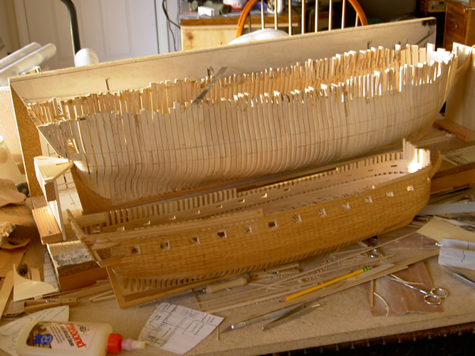
The picture above shows the model with planking completed on the building board. In the foreground
is the Vandalia nearing completion. I always have several projects underway at the same time.
I discovered that the upside down technique has several advantages. First, it is a much easier and
faster and stronger way to set up the frames. By securing (gluing) the stem and stern post (extensions)
to the building board, the keel is set up and squared first. Then, the frames set up easily and can be
squared readily as you work and do not wobble around as can happen when setting up more conventionally.
Second, if you follow Hahn's instructions and cut out the center part of the building board and lay out
the stations in pencil or marker on the board, it will further assist and make easy squaring up each
frame as you glue it in. And, once all the frames are set up and the hull planked, you can leave it
securely fastened to the building board if you like while you work on finishing the inside of the frames
if you are adding interior detail, or simply want to fair the frames on the inside as well. And third,
once the frames are glued to the keel and the building board base, the structure is very strong and is
much easier to plank. And lastly, as Hahn points out, once the hull has been planked, if you leave it
on the building board and build a box to fit it, you have an excellent container to store and protect
your work in progress. In my case, Raleigh spent nearly five years in the box between building sessions
One reason for the hiatus in working on the Raleigh was, among other things, I had other models in progress.
The Vandalia had been started before the Raleigh and it needed to be finished first, which happened in
2004. Also, around the same time, I started a model of the Constitution in 1:64 scale, mostly because
I was interested in the differences between the "light" frigates such as Essex and Raleigh and the
"heavy" frigates, such as Consitution, which was designed only about twenty years later. I thought
having two hulls, one of each type, would illustrate the difference. Below is a photo of the hull of the
Raleigh (off the board at last) and the Constitution, in the same scale, to show the contrast. Note also
that the Constitution is set up on a conventional building board/framing jig. I don't do that much anymore.
For the Raleigh model, frames, timbers, ceiling, trim pieces, head timbers, masts, spars, blocks and various
miscellaneous wood parts (gun carriages) are hard maple. The hull is planked in red oak. As with the
Vandalia, I planked one side of the hull and one side of the decks to expose the timber framing
of the decks. Deadeyes, ship's wheel,
and cannon were turned from lignum vitae, and some mahogany and walnut veneer was used in making
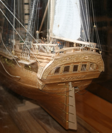
interior cabin bulkheads. The fancy work on the transom and the trim of the quarter galleries
were carved of boxwood as well the crew men. Metal fitting were fabricated from brass sheet and wire.
The only purchased
fittings used on the model are the belaying pins.
All the lines for the ship were made up of cotton threads and yarns spun and plied up into
ropes and cables of appropriate diameter, using Steel's as a guide to sizing of cordage and also of blocks.
For more information about making up the lines, including tables of my calculations for rigging size,
listing of the actual yarns used, design of the rope machine, and tips on rope-making materials
and technique, go here.
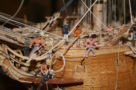
I made the sails from very light weight cotton cloth, and modeled some furled and some deployed. The
"story" for the model is that she is shown leaving anchorage. The starboard anchors are stowed, and the
forward portside anchor is aweigh at the cathead with crew passing the fish line through the ring for
the final steps in securing and stowing the anchor. Aloft, topmen have released the foretopsail and another
crew is unfurling jibs. Another group is bringing aboard the last of the ship's boats for stowage in
the waist. On the quarter deck, the captain and his officers confer, and two marines stand guard at the
forward end of the quarter deck. Although I have liked making models with half-planked hulls to show
details of construction, over time I have gotten more interested in modeling the processes of sailing.
The Raleigh is a step in that direction, but in retrospect, I perhaps should have planked the model
completely and painted her to more realistically show what she might have looked like in action.
The Anchor Hoy, the Benjamin W. Latham, and the Constitution are later models, more properly
considered dioramas, and made to show how things worked as much as what they looked like.
Following are some pictures of the model in progress and after completion.
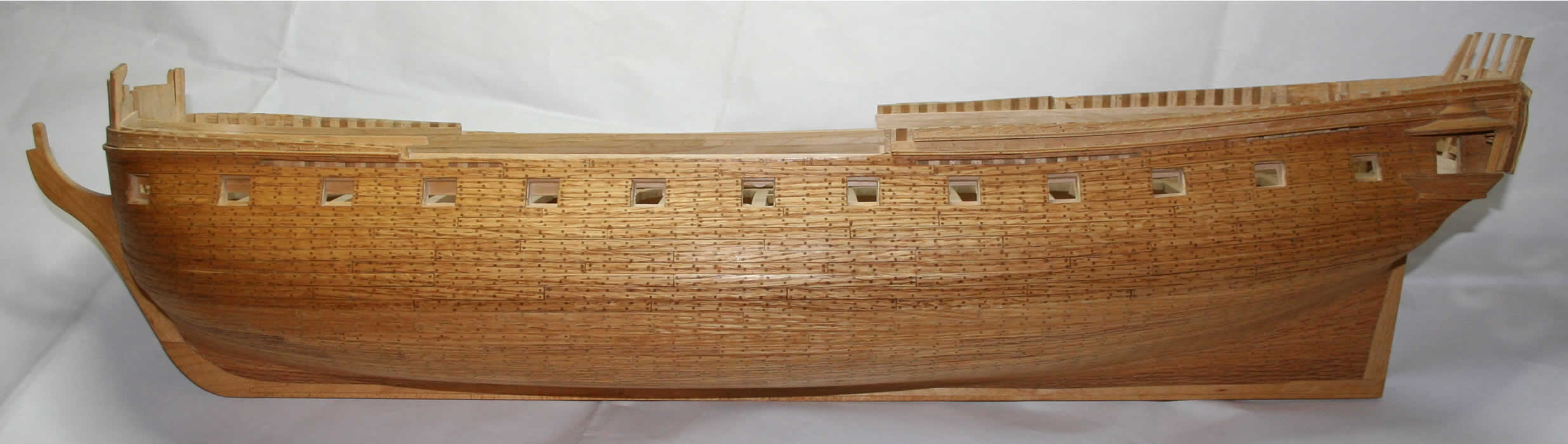
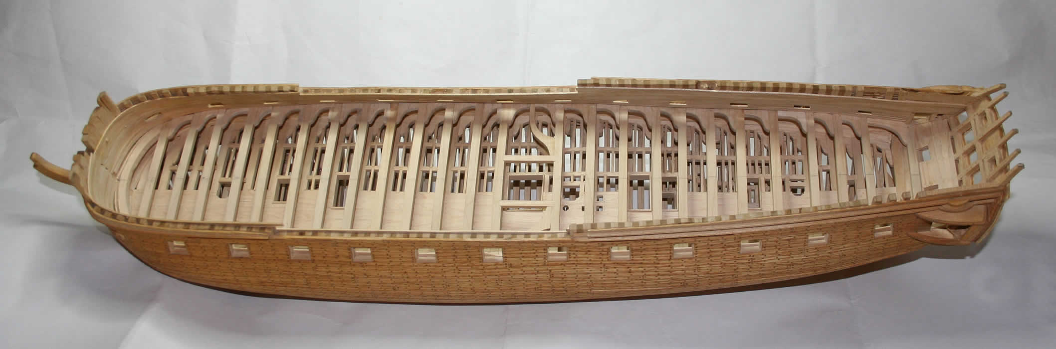
Hull of the Raleigh after cutting it from the building board and trimming the frame extensions
close to the upper edges of the planking. Transom timbers are left long at this point as they
will be used in framing transom windows and railing.
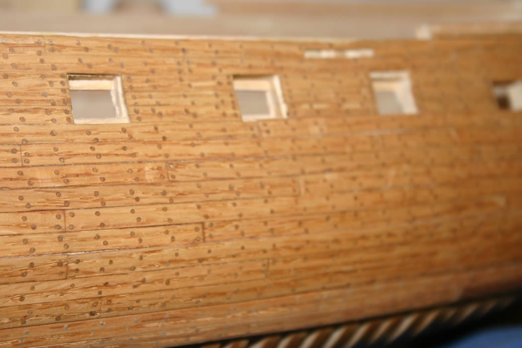
On the left is a close up of the hull planking. I use red oak for the planks, milled down to scale
thickness of 4 inches on the prototype (1/16" on the model). I fasten the planks with waterproof
yellow carpenters glue using wooden pegs to secure the individual planks as I move along. I make the
pegs by splitting white wood tongue depressors (available in any craft store) selecting ones that
split straight and do not have diagonal grain or weak spots. I split them down as I need them, to about
1/16 inch wide, then carve them to a long rounded point and hammer them in with a small lignum vitae
mallet I made for that purpose. Depending on the model and the area I am working on (outside planking
versus ceiling, for example) I use a drill size from #65 to #75 to drill the hole for the peg. This is
a remarkably fast and secure way to plank a hull. With a little practice, and a glue with an open
time of about ten minutes, I can install a plank completely by pegging each end and a couple of frames
in between, then move on to the next plank, at least when working on a fairly straight run. Later I go
back and peg the plank down to every frame as shown. As I work, I check the plank width and taper planks
as needed to keep a full run fore and aft for each plank. This is also a good technique when you are
putting planks on a curved surface, as the pegs hold very securely and almost eliminate the need for
clamping. The technique is less useful on hulls which are plank on bulkhead, as the long runs between
bulkheads are a problem, but for a model with proper framing, it is just about perfect. Also, I think
part of the reason the pegs hold so well might be that the glue used is water based, so the wooden
pegs likely absorb some moisture and swell a little resulting in a tight fit. That plus the fact they
are hammered home.
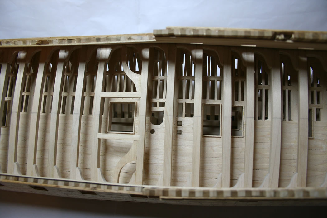
On the right is a photo of the stern/transom timbering at a later stage of construction. The berth deck
timbers are in place and the transom has been planked and the fancy work applied, but you can see
how the transom/stern timbers are used to frame the windows, and later, extended up to form the railing.
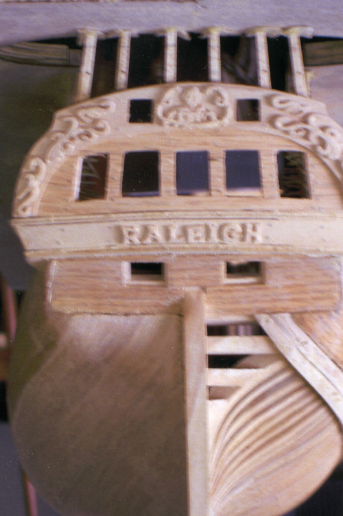

On the left is the original transom with detail and fancy work carved from maple. Note also that
in that photo, the hull is still glued to the building board.
On the right is the replacement transom and trim carved from boxwood. An improvement, no doubt. I
find that boxwood is unsurpassed to holding fine detail and have pretty much converted to using it
whenever fine work is needed, including head timbers and figureheads. My boxwood supply came to me
when a neighbor in Virginia asked to borrow my chain saw to cut down some boxwood shrubbery at the
front of their house. Since I don't loan tools, especially chain saws, I responded that I don't loan
tools, but do rent them, and a man comes with the tool And in this case, the rent would be that I
would get to keep the boxwood stems for my wood supply. A good trade, as in the ensuing nearly
twenty years, I have not used even 10% of my stash.
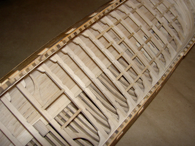
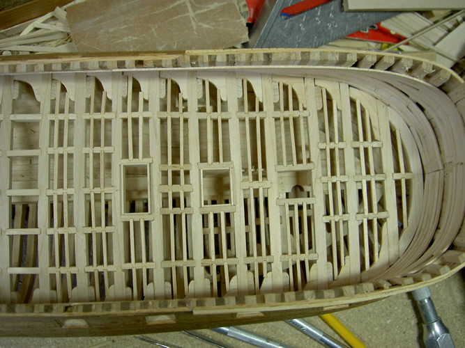
The photo on the left shows the timbering of the berth deck underway. The main timbers are in place, and
the carlings and half timbers being installed. Note the notches in the large timbers, which accomodate
the tapered ends of the smaller timbers for a secure joint.
On the right you can see the breasthook for the berth deck in place. Also, you can see some deck timbers
below the berth deck, which is the orlop, a deck which did not extend the length of the hull.
Once all the timbering is complete, I install hatch coamings and any other needed timbers and plank half the deck.
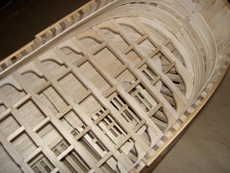
On the left there is a picture of the berth deck timbering completed, hatch coamings in place, deck
ready for planking.
On the right, the much larger deck beams of the gun deck are installed above the berth deck, which
has been half-planked.
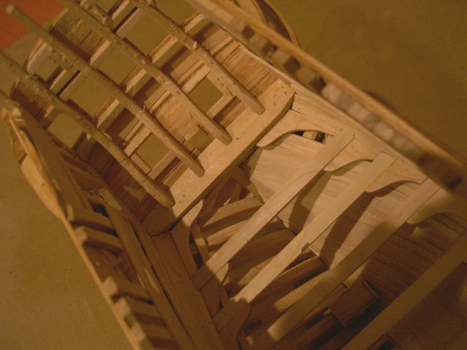
All the main timbers of the gun deck are in place. Next step is to install all the intermediate
timbers between the main timbers, then add timbers for bitts, coamings, planking and so forth.
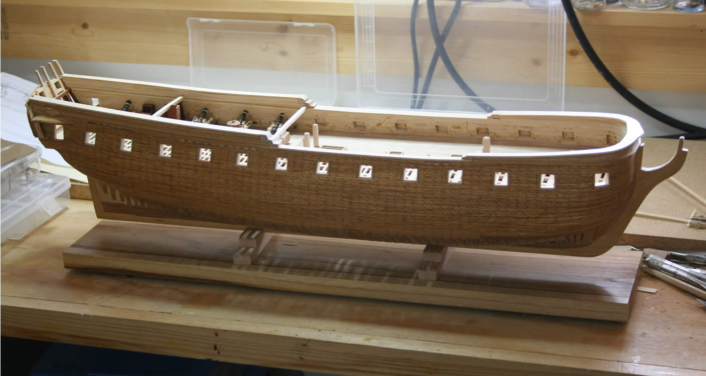
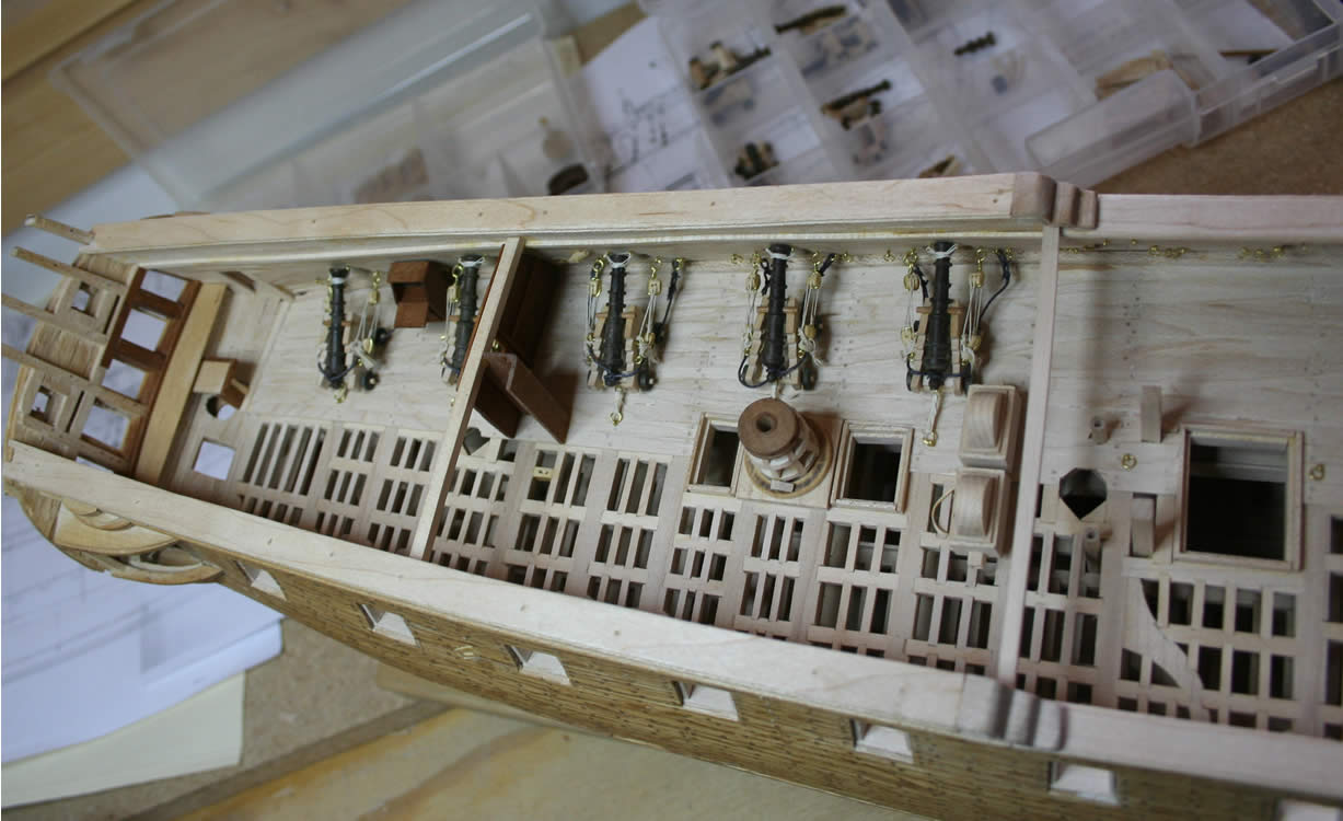
A picture of the model with the gun deck half planked and various detail added: coaming, capstan,
bitts, etc. Since the gun deck was uncovered in the ship's waist, now is the time to add detail
to that part of the model. Also, some finish work has been done in the area that will be the
captain's cabin, including the rudder trunk and an interior bulkhead.
Another picture from the same date shows some additional detail. Guns are installed in the
portion of the gun deck that will be under the quarter deck and will be shortly installed in
the area beneath the forecastle. First railings are on and construction of the quarter galleries
has begun.
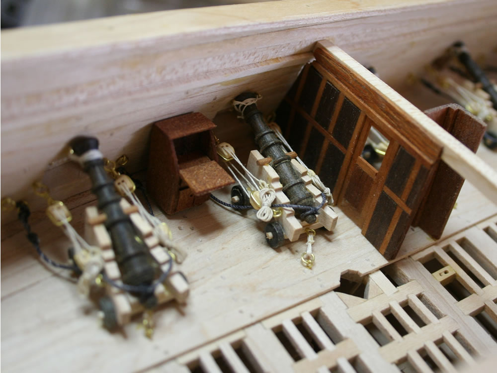
Two shots of the detail in the cabin which will be covered by the quarter deck. On the left you
can see the guns in place, framing around the transom windows, the rudder trunk cover, pumps,
lower capstan, and so forth. On the right is the interior bulkhead separating the captain's
cabin from the general cabin and the captain's small writing desk between the two cannon. Most of
these details will not be visible once the quarter deck is in place and partially planked.
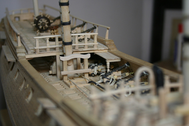
View of the deck at the main mast looking at the quarterdeck. You can see the wheel, the upper
capstan, and the several six-pounder cannon on the quarterdeck. There were also two on the
forecastle. The hull is pretty much complete and ready to start the rigging.
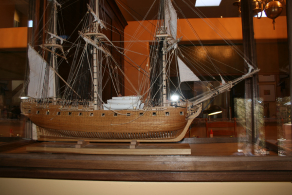
Views of the completed model. On the left, on the table top. On the right, in her case. The
case is walnut framed and has LED lighting in the top. I make my cases myself and always make
sure there is good ventilation and use LED lighting that does not emit UV wavelength light.
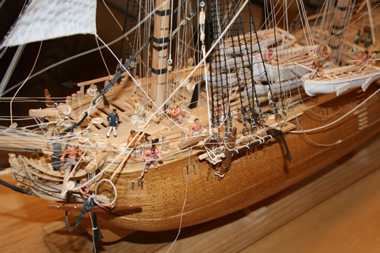
A general shot of the bow with activity related to retrieving and stowing anchors. On the right, two
men are passing a heavy line through the anchor ring preparing to secure it while a third man
stands on the edge of the rail, with the fish line ready to hook the anchor shaft to haul it
up and against the hull. The man with the fish has a line passed around him to prevent falling
overboard. The fish line passes through a block on the "fish davit" then back to a tackle with the
hauling end led inboard so the men can haul up the heavy anchor and stow it on the channel.
 >
>
Just aft of the man fishing the anchor, another crewman has retrieved the anchor buoy and is
coiling the anchor buoy line to stow it. Note the lashing securing the second portside anchor
to the channel.
The right side picture shows a general view of all the activity around retrieving the anchor.
There is a midshipman standing on the forecastle deck "supervising" the work of the crew.
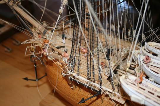
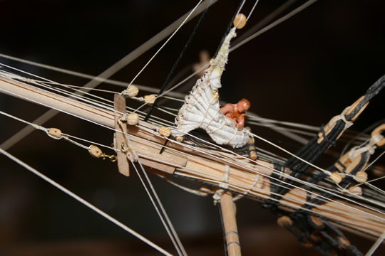
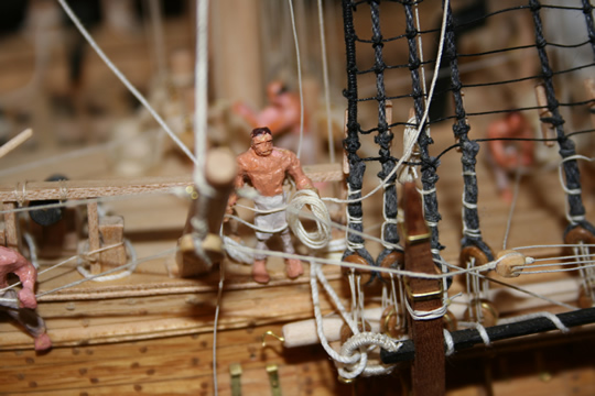
Another shot of the general activit on the forecastle when weighing anchor and preparing to
sail. A crew member is on the bowsprit doubling with the jib boom unfurling the jib as the
ship catches the wind and wants to gain speed so she will answer her helm.
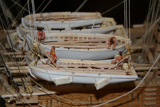
Meanwhile, crewmen are bringing aboard the last ship's boat, which has just brought the last
officers and crew on board. The boat is hauled aloft using the lifting tackle on the fore and
mainmast and swayed inboard to be lowered on the stack of boats in the waist of the ship.
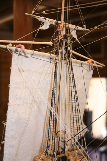
And the top men are finishing up after releasing/unfurling the fore topsail by coiling and stowing
the line used to furl the sail. Another crewman is holding aloft the stunsail boom to keep it out
of the way.
The captain meets with the first mate and sailing master on the quarterdeck.